
When we moved into our house our old table was far too small and even with another donated table pushed against our round table it still didn’t fill the room.
After many years the time had now come to replace this but trying to buy a table in this size would have been 0000’s of pounds. So the only was forward was to build one!
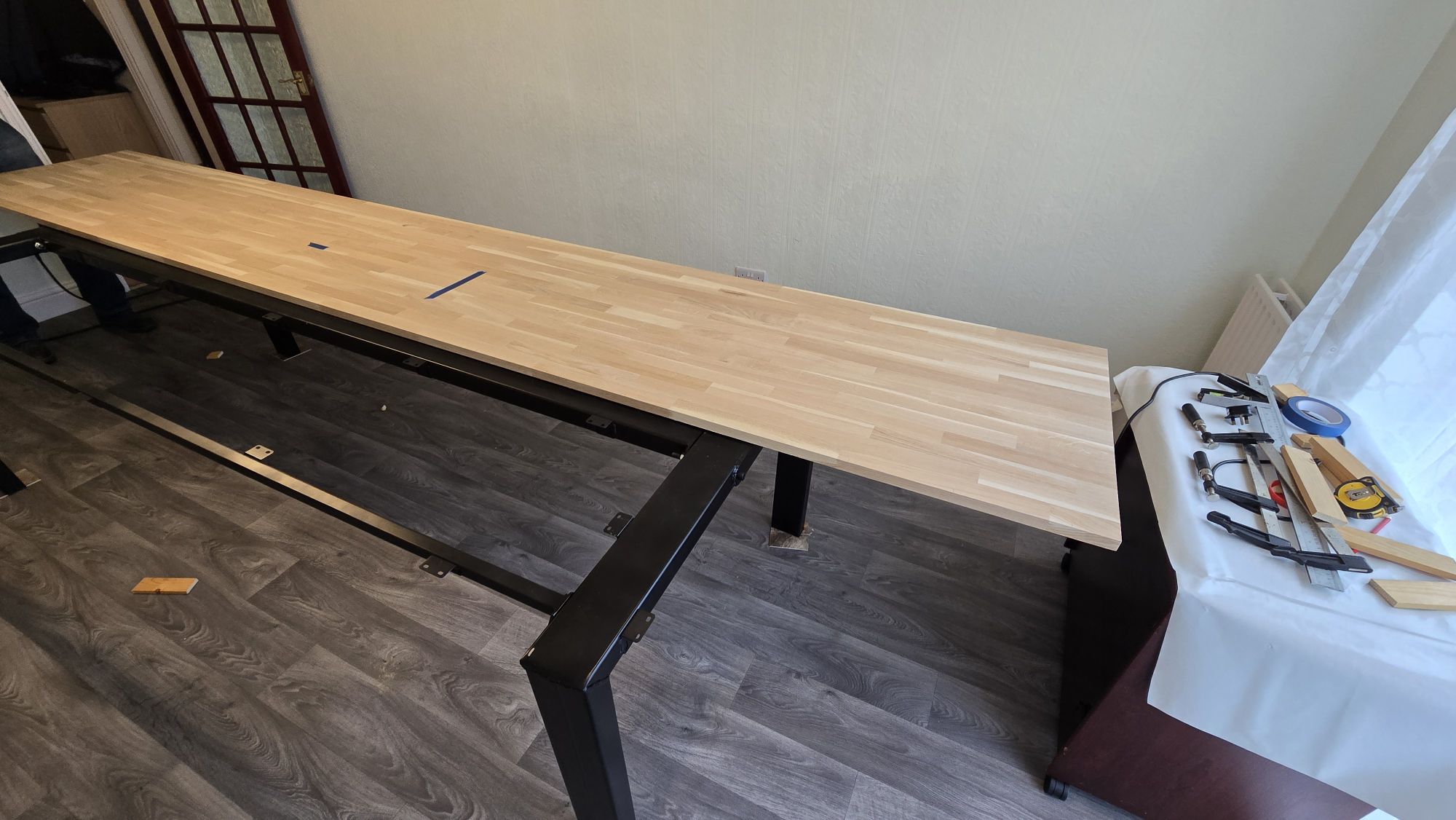
After a measure of the room and some research, it was decided to make a metal frame and wood top, I was going to use a MDF wood top but then found a site selling 22mm sold oak kitchen worktops in a 635x4000mm size, so with 2x off these ordered with a plan to some how join them together.
With the top found and knowing what size we were looking at, next was onto the frame. Looking at some metal sites, what became apparent was when you go up in size so does the thickness. The table could be heavy but needed to move able and also the price of the metal is based on weight so thick legs also means more cost.
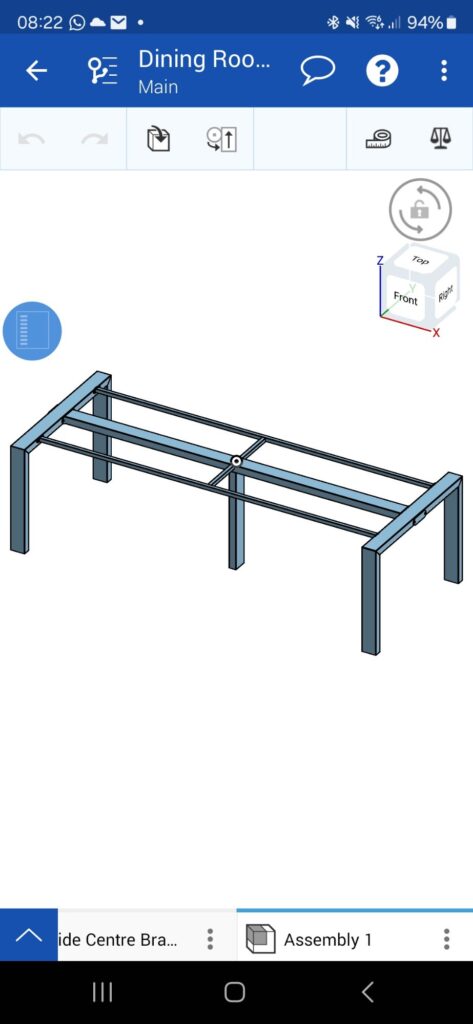
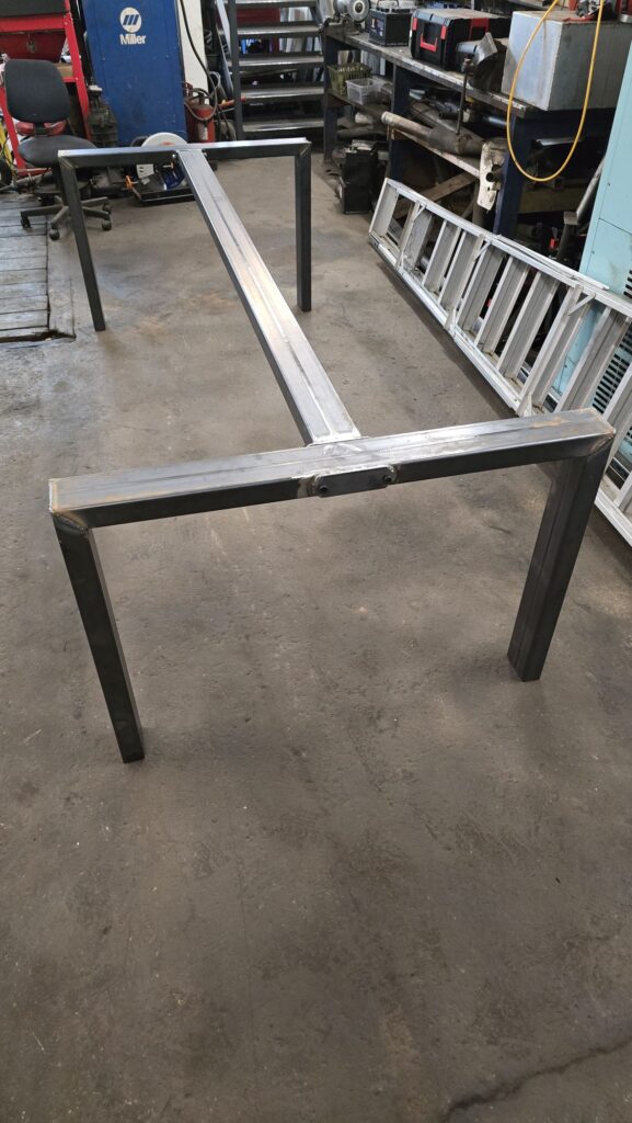
Now onto the design, knowing there was going to be a seam down the middle of the table i wanted both side supported to take the load off the joint, I went for a simple upside U at each end, main beam that runs down the middle and then 2x smaller side rails the rails and ends all bolt to each other, quick design on CAD and we were all set.
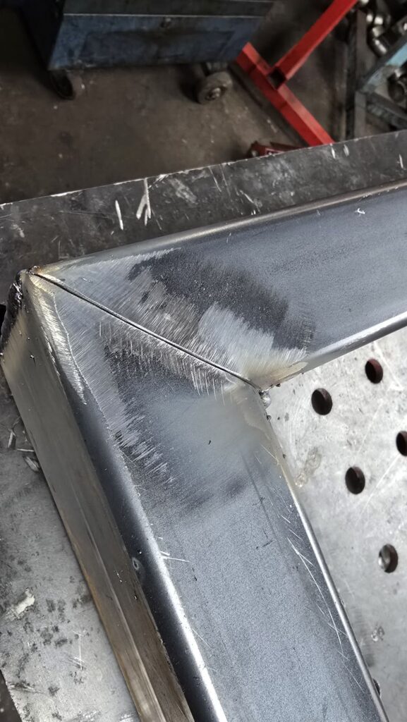
After printing out a parts list so I could cut all the parts to the correct length, the legs each end I went for a 45deg mitre joints, I could have just done a butt joint but if anyone look under the table I would like it to look nice, I also added some mounting points for wood top.
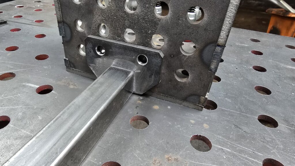
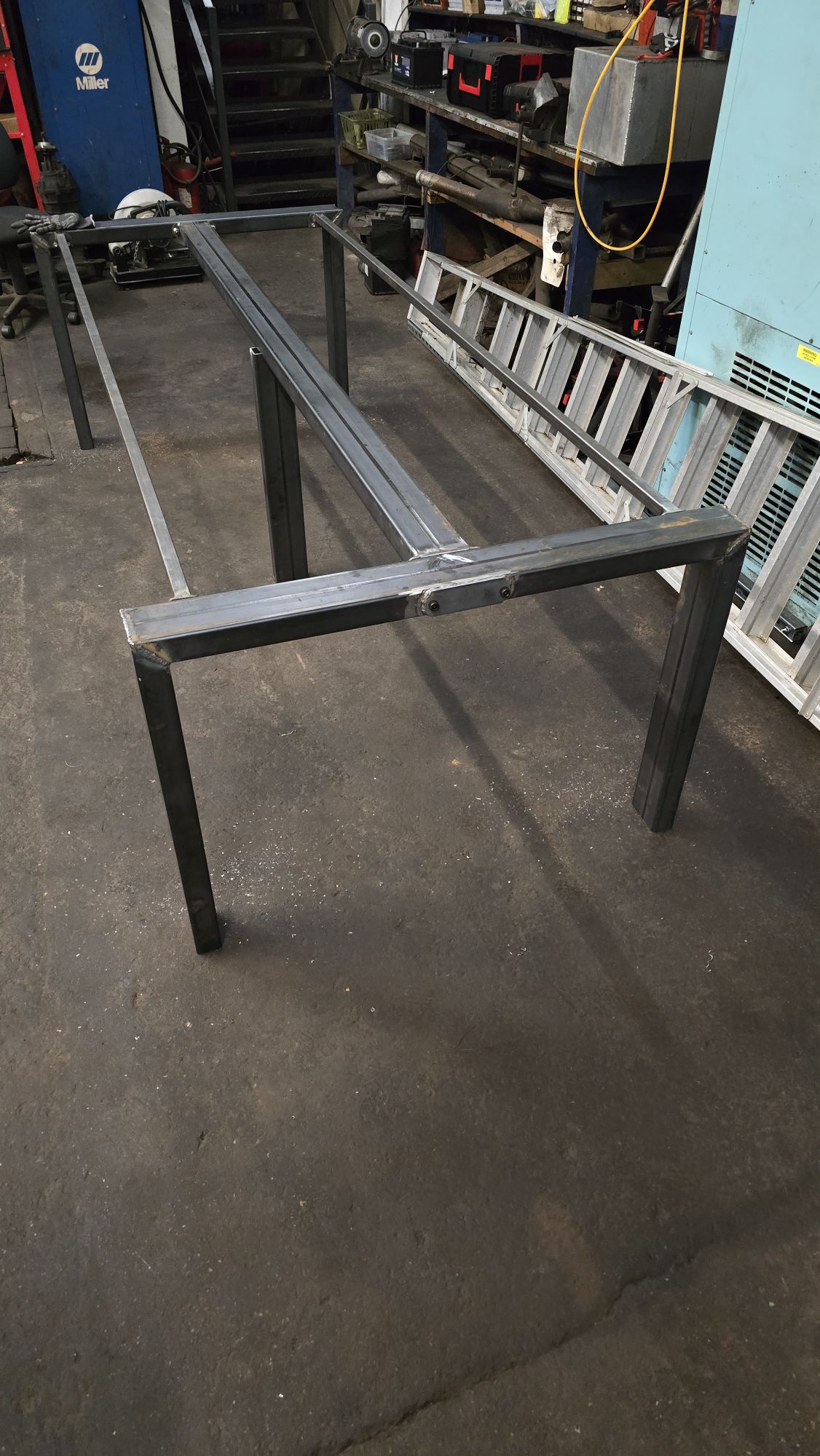
Out off some 5mm metal plate I cut some bolt together flanges and these got welded to the end and load spreader on the other side. With everything cut and made it was now time to start welding everything up
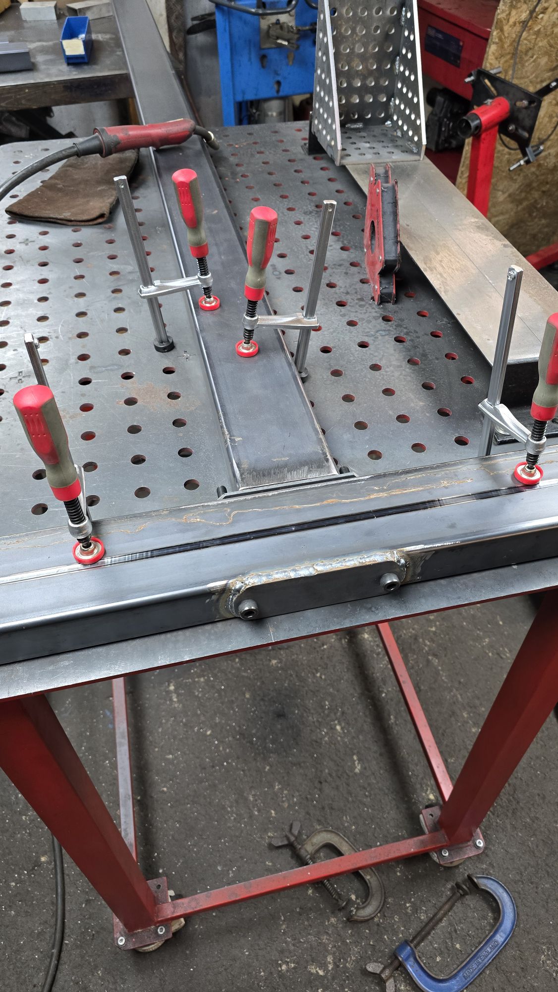
Once everything was welded, it was time for a test build and load test, with the main frame holding my weight. This was classed as a pass. Now it was time to clean the welds and any sharp edges once cleaned up it was all stripped apart again and taken to my house for painting.
Once painted, I managed to find some plastic bungs that closed the end of the tube\spread the load on the floor, with everything ready it now time to build the frame in the dining room.
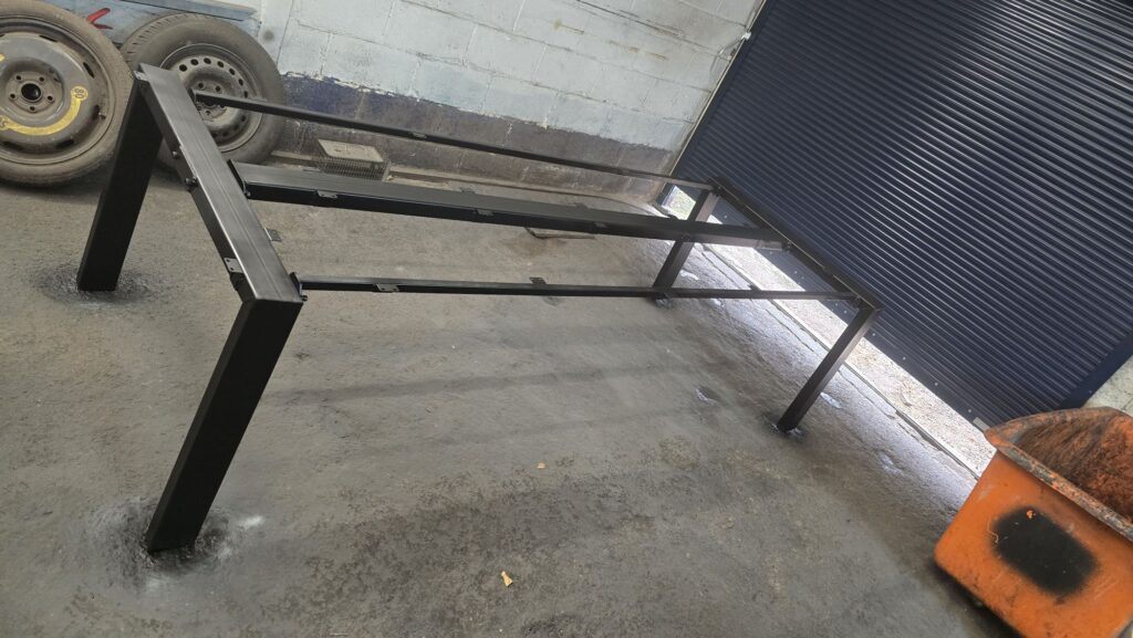
With the frame built I applied self-adhesive closed cell foam along the top faces off the frame to stop creaking noises. Next step was to test fit the oak worktops with them side by side we marked the length and cut the excess off, next we checked which side were best and what ends matched the best with these marked the worktops were pulled apart and using a borrowed biscuit joiner holes were made in both worktops.
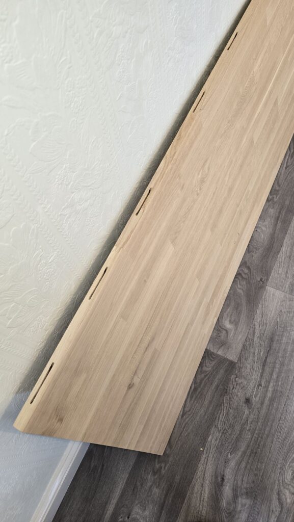
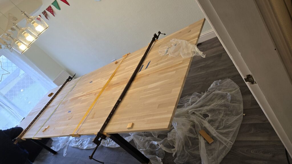
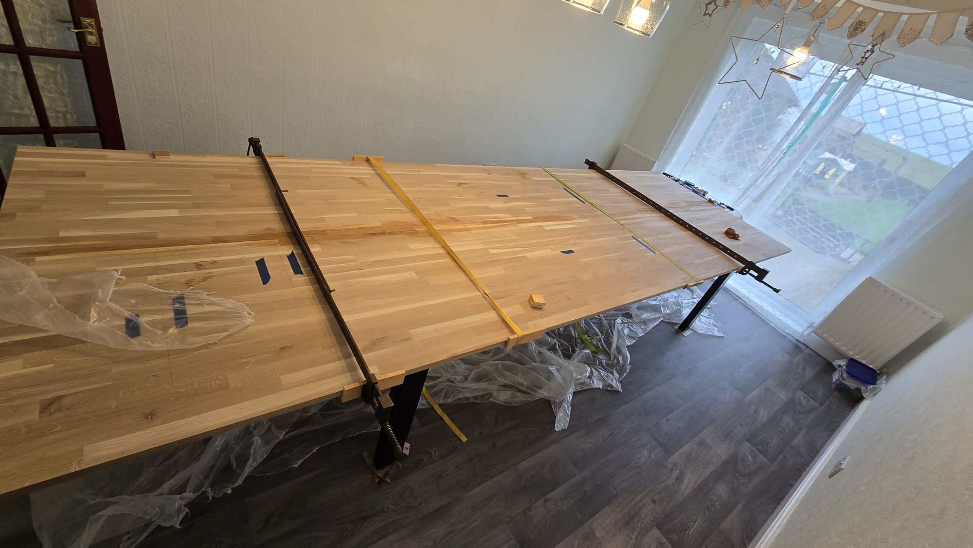
With a plastic sheet over the middle to catch any excess glue and some borrowed clamps (also my home made clamps, spare metal/wood bars and rachet straps) all ready. Time to glue, with glue and biscuits added once done the 2 half’s were clamped together and left to dry.
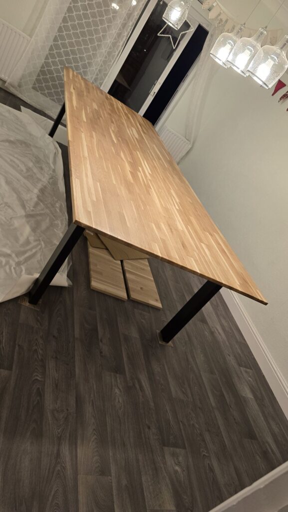
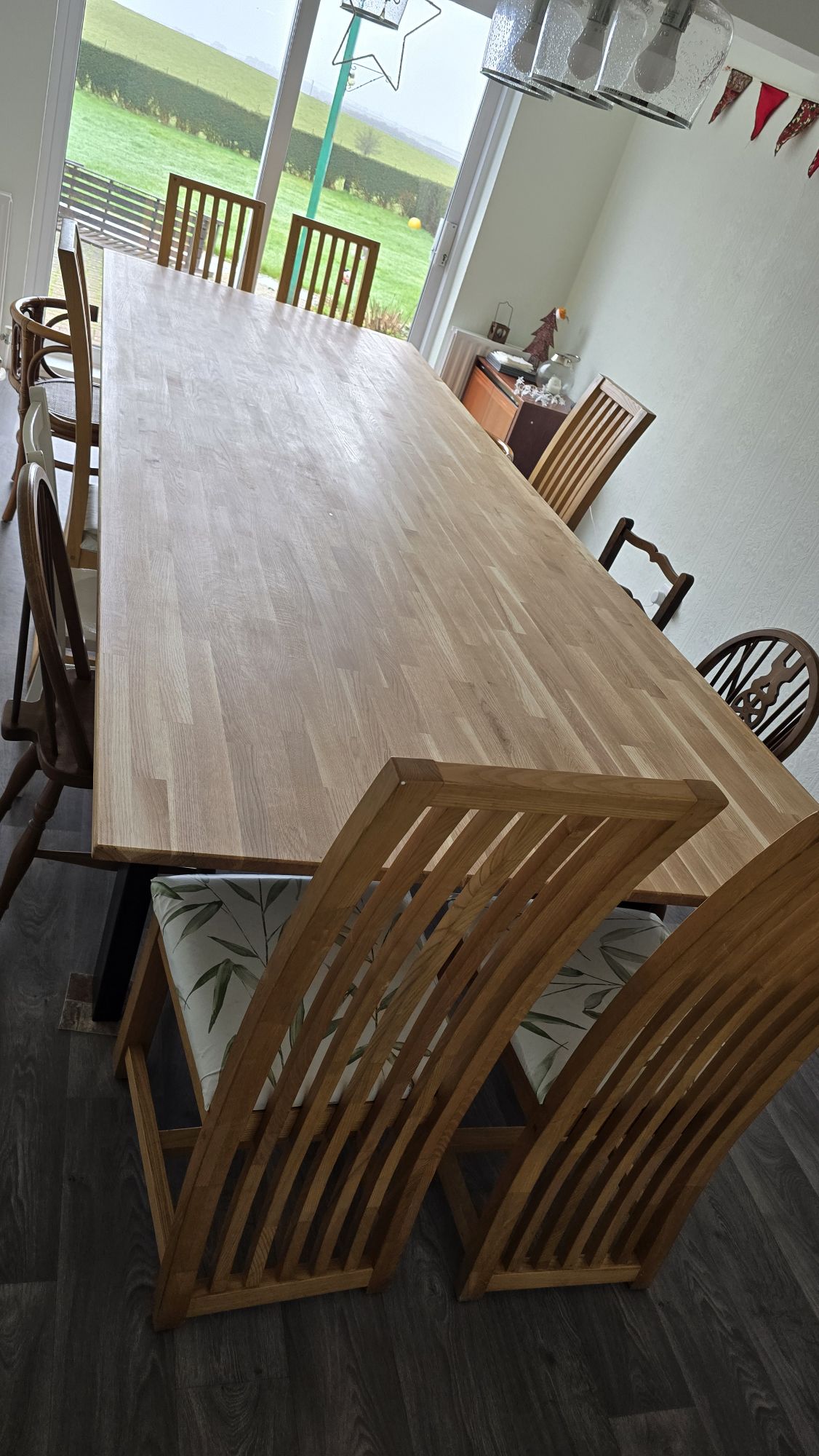
Once dry the joint was filled where needed. Using a hand held router a chamfer was added top and bottom all the way round. With this all done and it was time to sand the complete table, after clearing up and cleaning the table got treated to many coats of osmo oil.
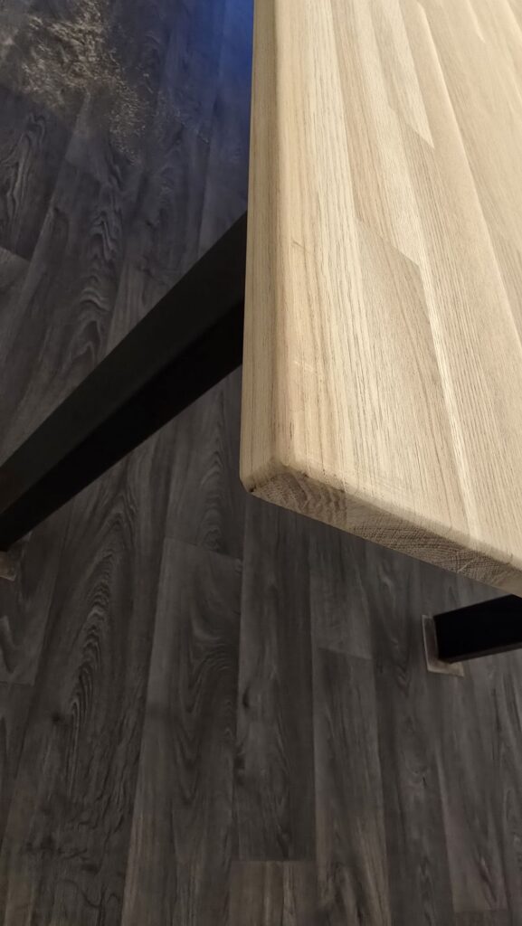
Once dry it was time to use many wood screws to mount the metal frame to the top and admire the finnished table
When winter times come in my van its always a horrible time of year as the 2.5tdi T5 is a slow warming engine and the windscreen is so big it hard to scrape the ice, after getting a crack in my current windscreen I started looking at if it possible to retrofit the heated screen out the new T6 into my T5.
Planning:
After phoning the windscreen company and asking if this was possible and they said the scenes are the same shape/size this was the major part out the way I now started looking at what else was needed.
Issues:
There are some changes that would be needed and that was there no longer an aerial in the windscreen (no problem as I had fitted a shark fin aerial for FM,DAB and GPS at the rear.
Also the mirror is completely different as all heated windscreens come with rain and light sensor in the screen.
The windscreen would also need wiring but decided this could be done afterwards.
With it all looking good the windscreen was supplied and fitted by Corby Windscreens.
Next was to source a mirror and and after a little hunting found a 2nd hand Skoda Kodiaq one for £14 (Part number – 3G0 857 511AF) with this ordered and new trims from VW this was fitted and clipped into place (this makes the inside look much more modern.
Wiring:
This is the longest and hardest part of the job, (Wiring diagram to follow later)
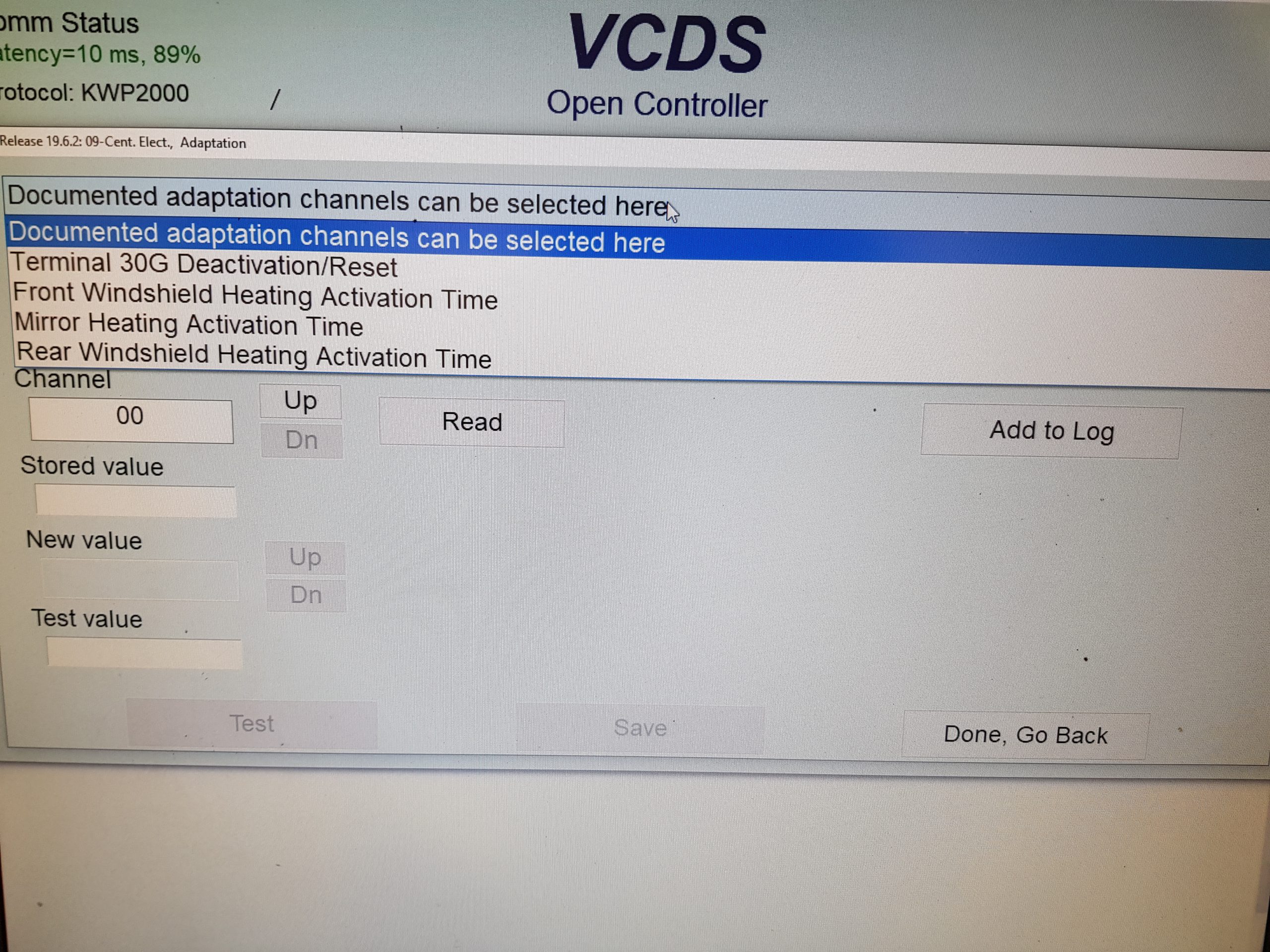
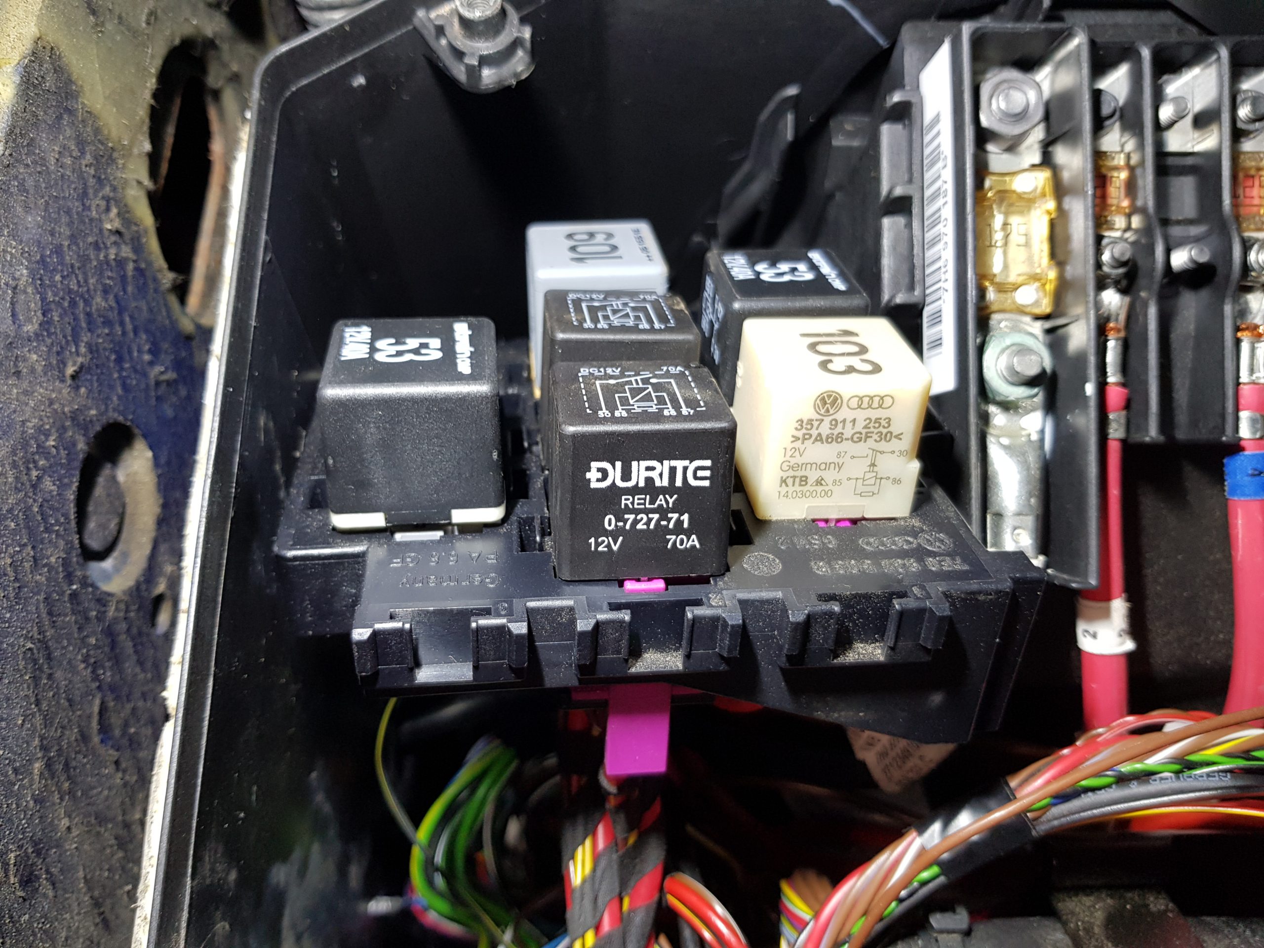
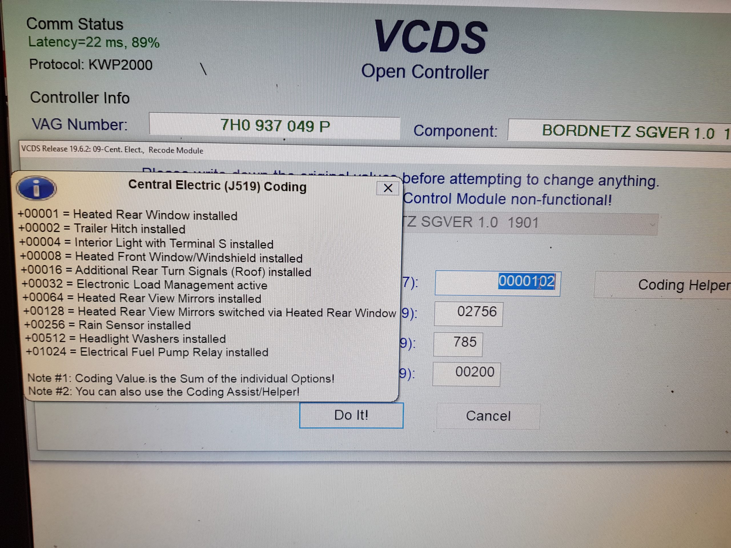
For me it has to look as factory as possible so I matched as many connectors and pins as possible, I also mounting the relays in to the relay carrier under the battery. My van didn’t have heated rear windows so I decided to use the original heated rear wind switch and connect this the Central Electric J519 as per VW heated rear windscreen is wired (reason for this was it gave diagnostics to the heated windscreen, it also let’s you change the length of activation with VCDS) after plugging in my van to VCDS and checking it listed heated rear window as a option but also in the list was heated front windscreen! Even better.
After find a pin out data for the J519 and finding mine has the pins where heated windscreen should fit, a quick wire up and testing found it picks up the switch press but that is all and doesn’t turn anything on! On the pin data it lists heated windscreen as “not delivered yet” back to connecting the heated rear window route again.
First thing was to make the relay looms and holders, I used the VW relay holders that clip into the factory relay carrier under the battery – The windscreen is 2 separate system, the driver and passenger side runs it own circuit this is why 2 relays are needed and also to handle the current

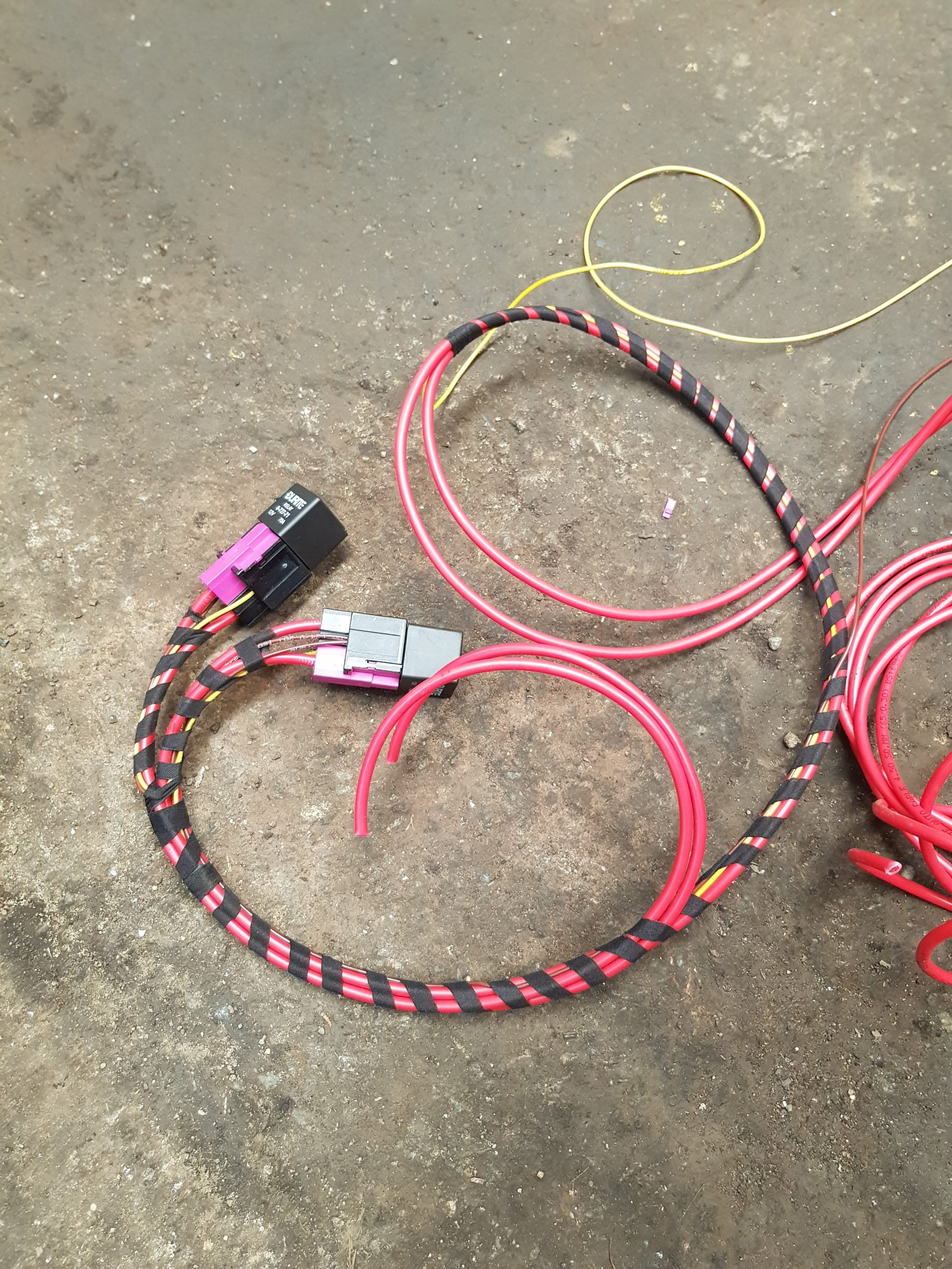

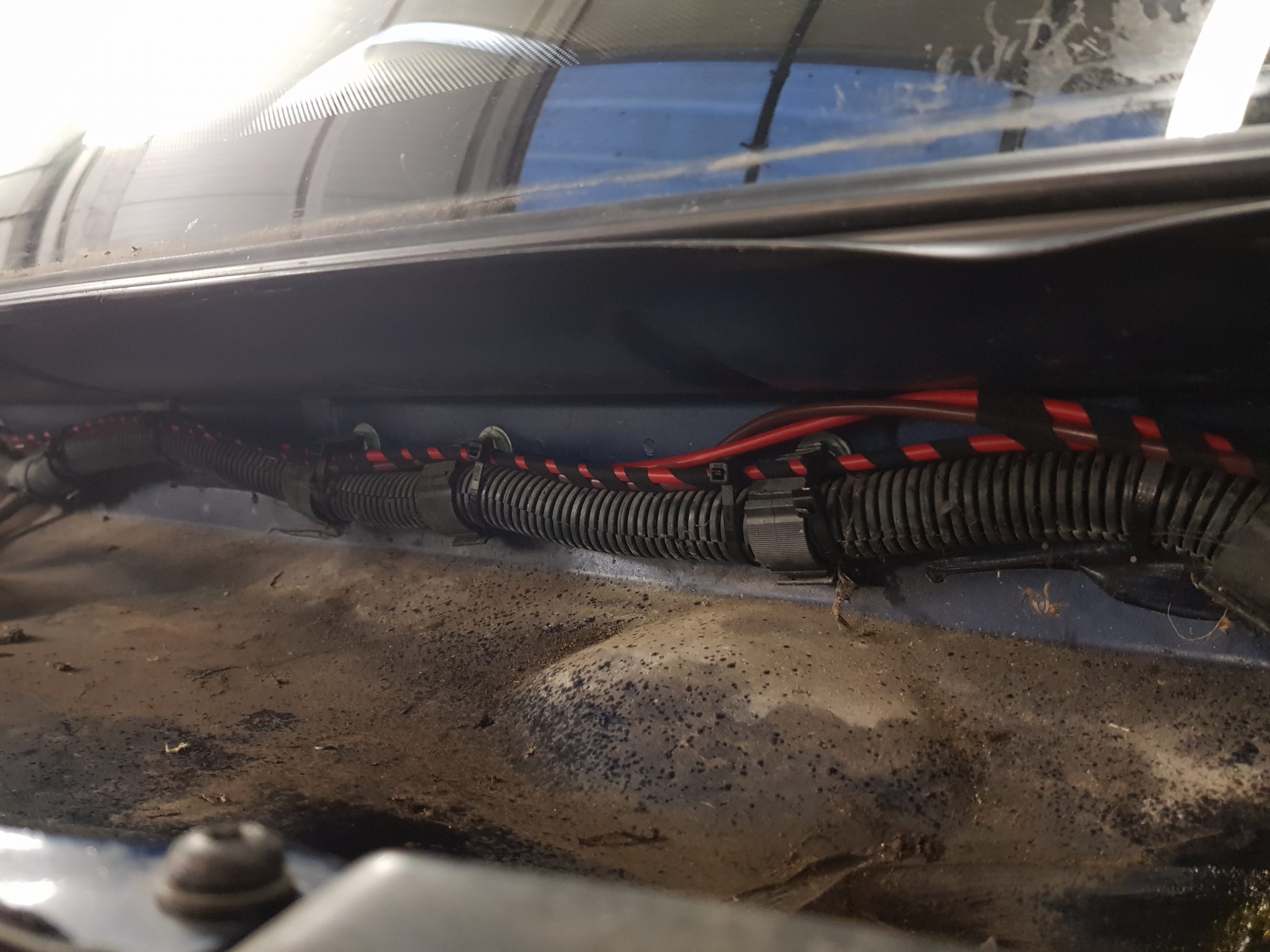
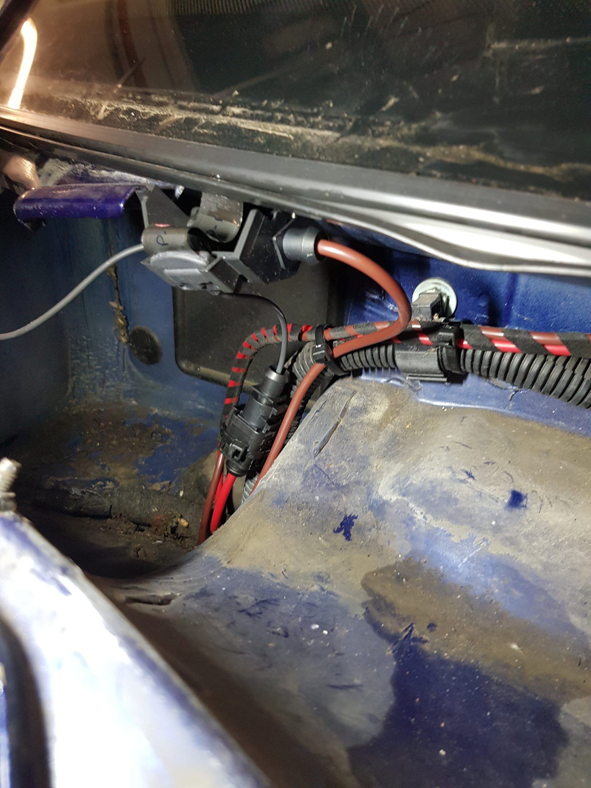
Next part was to take a fused feed from the battery distribution point next to the relay carrier


Once out the power wires were run up towards the windscreen and signal wire was run into the van and towards the J519 – Central Electric unit


No onto the switch and inside of the van, as mine is a van I didnt have a heated rear window so used a rear window switch, this is wired into the J519 – Central electrics and J519 then provides the feed to the relays, this setup was used as with the diagnostic tool I can adjust the time the J519 keeps the screen on for before automatically switching off.


Once this is completed and all wired in next step is some coding and changed in the J519- Central electric ECU. I needed to add +1 to my original coding to turn on the heated rear window function (for my front window) Once done exit out and lock the vehicle for at least 5 minutes. Now unlock and connect scan tool again and check coding has changed. If yes you can now go into adaptions and change the length of time the window stays on for.

Check everything works and then put everything back together, wait for the frosty morning and enjoy your hard work.

We had some new windows fitted in the bay window of our house to replace the old wooden ones, the new ones are nice bright white triple glazed windows and very nice and make the room very quiet, but as the old curtain track was screwed to the wooden window frame we needed a new curtian pole.
Now quick look online showed universal poles for about £60 but these looked quite poor and required different brackets buying. Now I also found a site that would make pole with bending and brackets to suit but quick pricing showed this was going to be £300-400! This seemed expensive to me and I could make something better and cheaper.
As I already own a JD2 tube bender and 1″ former this sounded like a good base to make a pole, I found a website called metals4u and these listed 5 meter length off 1″ aluminium tube for around £12. But would it bend??? Checking some specs found that 6063 is a good workable spec and the tube from metals4u is 6063, so some quick measurements were taken.

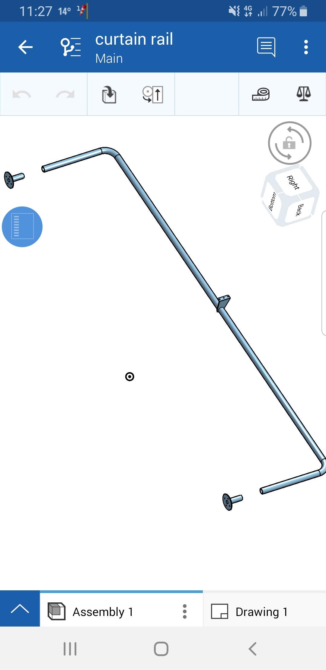
Now because our bay window has return in the walls the hole in the wall is narrow compared to the bay window, so I designed the pole to mount the return on the walls and the centre mount is a ceiling bracket. I ran a 80mm offset from the window frame. A quick design in some CAD software called onshape looked good so I ordered 2x lengths of 25.4×1.6mm by 5000mm(1 spare incase it went wrong), 1x 22.2×1.6mm by 500mm and some 2mm flat plate.
Once the order has arrived I started by carrying out a test 90deg bend, cleaning the tube and former and using a lot of lube on the former it seemed to bend very nicely (I also marked the tube so I could work out the loss round the bend) with the measurements I proceeded to bend the other side and made the curtian pole I left the ends too long because it could cut these down later.

JD2 Tube bender 
JD2 Tube bender with tube 
Test and bend I used 
Finished test bend 
Taking shape
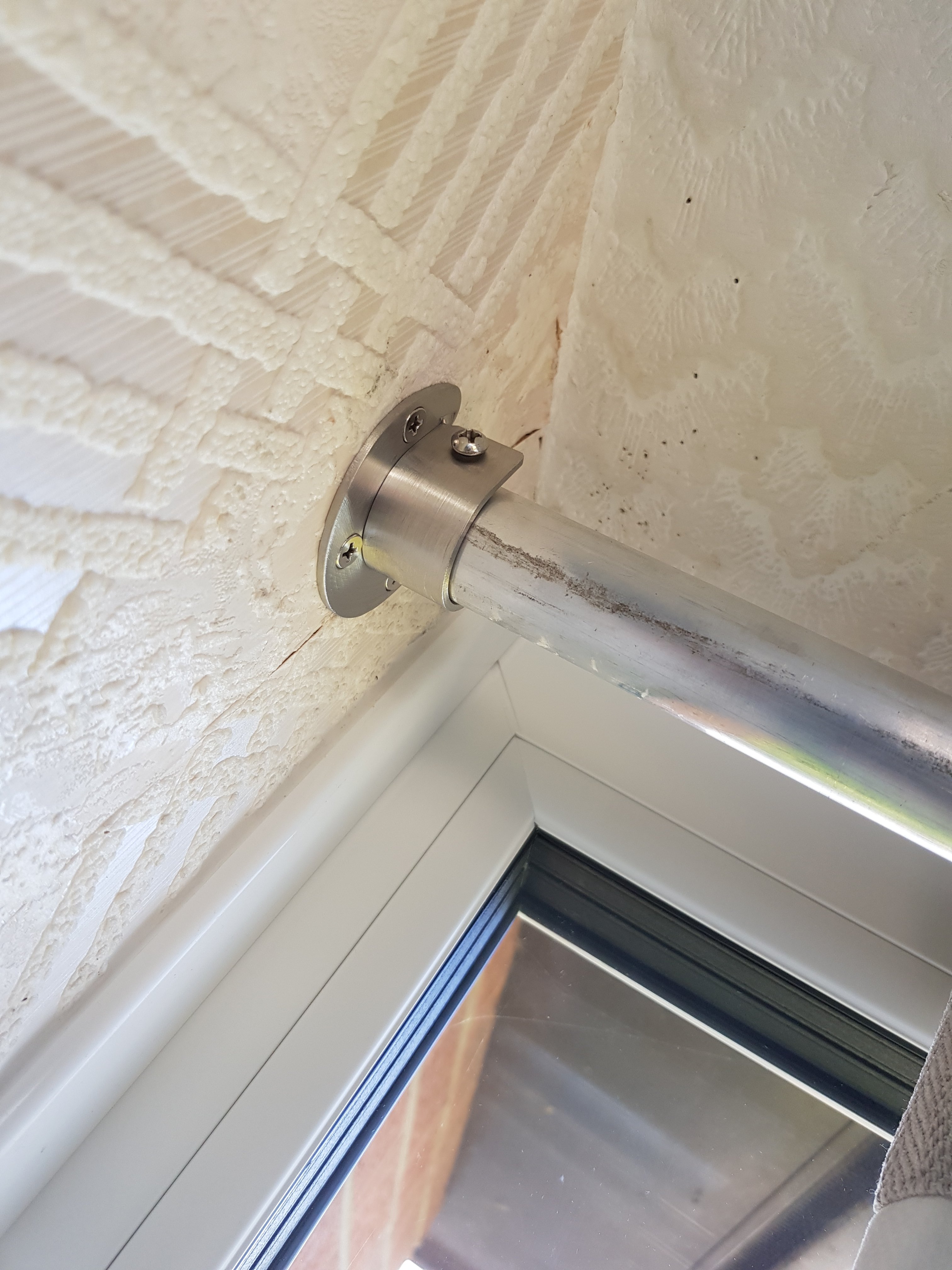
For the wall mounts I cut a 75mm hole in the 2mm plate and also a 22.4mm hole for form a donut or polo mint shape, then using a 75mm length of the 22.2mm tube I welded this onto the plate with the idea that the plate would screw to the wall and the rail would push into the smaller stubs, the problem I found is that was there not enough clearance and also the wall were not straight! While looking for curtains I found the perfect wall mounts and at £8 for 4 it was a no brainer to use these.
Now onto the centre mount the orignal idea was to cut some 2mm aluminium sheet and drill a 25.4 hole and then run that upto the ceiling with a 90deg bend and weld this to the tube see below

But, after some thinking I decided that the mount would need reinforcing around the screw holes and wouldn’t leave me any space to slot on the old mounts I changed to a steel centres mount. I brought some 12mmx3mm steel plate I clamped this into the vice with a ofcut of the 25.4 tube and proceeded to bend the plate round the tube to form a hook I then measured how far the curtains sat above the pole and added 10mm, with a 90deg bend added and 3x mounting holes I then painted it silver.

With everything ready it was now time for fitting, this was quite straight forward as everything was made to fit the windows. First I fitted the centre mount as the no up/down adjustment for this, with the pole now fitted into the centre mount I moved onto the wall mounts with it all mounted I removed the pole and put the curtains on and refitted the pole, job done now time for a beer
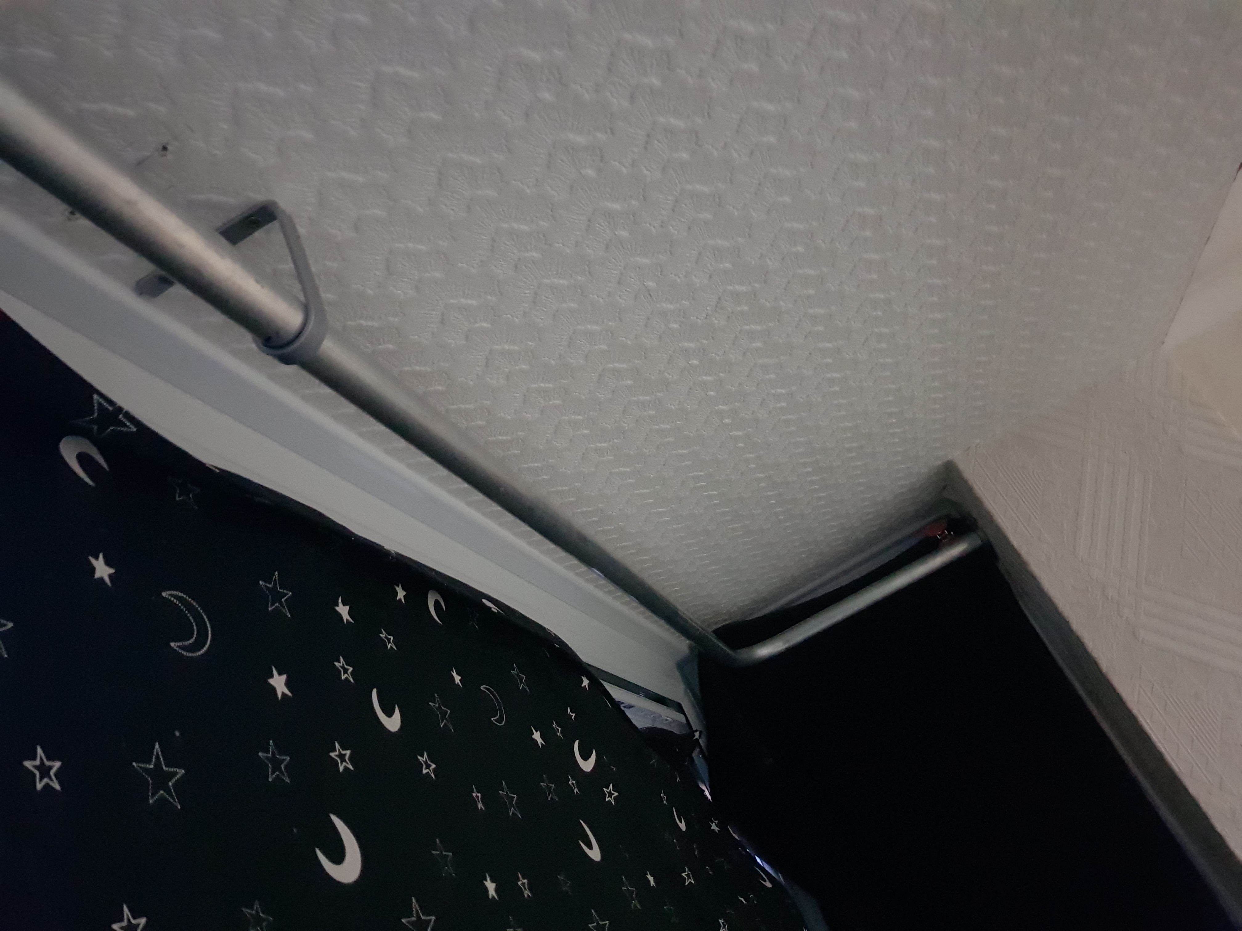
It was a short lived beer as I done a good job the wife turns up with some curtains for the downstairs bay! As I managed to bend the tube with only using the first tube I still had a spare 5 meter length of tube, so we started again and bent this to match the lower bay, this one is slightly different in that the middle mount needs to be wall mount and because they £96 curtains were in the sale for £11 they didn’t have the larger drop left so I needed to mount the pole inline with the top edge of the window, a hi-tech drawing this time.

This time as the load was being supported by the length I decided to triangulate the bracket but this all need to go up the wall. With the left over 12mm plate I made a new wall bracket that supported the pole and also the triangulation held the pole in place.

- All done – Total costing = £85
- Metal inc delivery £46 – Metals4u
- Wall mounts £8 – Amazon
- Sheet steel £9 – Ebay
- Curtain x2 £22 –
In March we brought a Rollplay VW Splitsceen camper kids ride on car this was the single wheel drive 6Volt model – It was being sold by Argos for a very good price as the 12v version was 4x the price!
After a summer of use the car has been really good apart from being 1 wheel drive on our bumpy garden the car get stuck and we have to go and push him, So i started looking at converting it to 2 wheel drive – You can go 12 volt conversion at this point but the extra cost was not worth it for me as I had a good battery and all the lights were setup for 6 volts
- Parts Needed:
- 2x 6 Volt Motors (18000RPM) <-This is what I used
- For 12Volt ones click here (12000RPM) and for (2300RPM) 12v motors
- 1x 6.3mm Terminals – click here
- Some wire, solder and heatshrink

Now start by disconnecting the battery and unplugging the old motor,
Now turn the car over and remove the wheels caps and pins holding the wheels on,
Remove the rear wheels and axle
Remove the screws holding the old motor and remove the old motor
You should now be left with a empty rear end.

Old motor 
Old motor with wheel 
Old single motor 
All motors removed
Test fit the new motors (note on mine the new motors fitted towards the rear)
I also had to remove a mounting hole off one side of the housing

New mounts towards the rear – old motor went forward 
New motor mounted differently 

tab that needs removing 
Tab removed 
New 6v 1800RPM motor 
New motors fitted towards rear
With them test fitted now remove and solder some wires to each of the motor terminals (remember to swap colours for each side so the motors run opposite directions) Heat shrink the wires and leave the excess to reach the connector.
New motors fitted towards rear 

Refit the motors and run the wires through, refit the axle and wheels. Turn the car back over and we will start on the wiring using a multimeter connected to the old motor plug check put the car is forward and check which way gives you 6 or 12volts (if you have -6 or 12volts the power is on the black lead) make a note what colour wire on the car side gives you positive power. Now connect each motor in turn and check they spin the correct direction (if you reversed the wire colours on the motor you should have the same colour wire for forward each side)
On mine I remove the old plastic plug from the terminal on the old motor, these terminals use the 6.3mm male spade terminals but struggled to find anyone that made the plastic housing so we reuse the housing with new space terminals. I connected both motors and ran a 3rd wire out for the headlamp output. With the spade terminals fitted i pushed these into the old plastic housing.

Next because we knew which wire was positive I could fit the diode for the headlamps, this stops the headlamps working in reverse, diode stop current flowing in the striped end, so it goes positive power into non striped end and the striped end towards headlamp. With this all wired in tape the loom and secure all wiring and plug everything back in.

Old wiring with diode for headlamps 
Reusing diode in new wiring 
Reconnecting headlamp wires 

Old 6volt relay board 
Finished wiring 
Finished wiring and secured in place 
All neat and taped up 


Now for the testdrive: After popping my 2 year old son in and sending him off all was going well until we got to the grass and the car stopped, (He shouts battery is flat daddy!) I walk over and try the throttle and it works fine, another 5 meters and it stops again. I think it my son stopped pressing the throttle but the next time it stops right by me and a second later I hear a click.
Back in the garage and checking I find a thermal fuse in the main battery lead, now with the 2 motors and grass it trips the thermal fuse, so next mod was to cut the thermal fuse out and replace with a standard inline fuse with 7.5 amp fuse, with this done next night we had a good drive all round the garden with no getting stuck and on pavement it faster but my 2 year old can cope with the extra speed no problem.
Due to some electrical work the weather station will be offline today (Thursday 1st August 2019)
Finger crossed will be back online by Friday 2nd August
As the old weather station was playing up (loosing communication with all sensors). I have saved up and bought and new weather station – Davis Vantage Vue
This new weather station has a greater range 300Meters vs 100Meters of the oregon scientific WMR200 – also seem much better built, downside are no optional extra sensors can be added to the Davis and the Davis is more expensive (When you factor in a data logger too)

The main display will live in the living room and using the IP data logger means I don’t have to put it next to the computer, This will give me more accurate inside temperature measurements and means I can keep an eye on the readings when in the living room

The Integrated Sensor Suite (ISS) make installation very simple, with only 1 unit to cover wind speed and direction, Rainfall, Outside temperature and humidity. using a TV aerial bracket and 1.5″ pole (3.6 Meters long) the sensor suit is mounted the gable end off the wall and sticks above the roof line to give as accurate wind measurements as possible.

With the weather station in and working next we moved onto the setup and web updates, As I run an old Dell Server in my home lab, I setup and new Virtual Machine (VM) this runs Windows and Weather Display software this is setup to receive the information over Ethernet from the weather station to the VM. This then logs the data and uploads it (In lightweight text format) over the internet to my website running Weather Display live(Flash player) and FreshWDL(Javascript)

Check the live weather out here:
Irchester Live Weather Station
Irchester Live Weather Station – Flash based (Requires Adobe flasher player)

I’m currently setting up my weather station in Irchester, The station (Oregon scientific WMR 200) is installed in a temporary position on the fence post for testing, The station display is connected by USB to a Windows 7 PC running as Virtual Machine on VMware ESXi 6.7 on a Dell R710 Server


This runs Weather Display software from Brian Hamilton with a 1 of fee for life. The software has evolved over time and I don’t think it the most user friendly but has many good features. This logs all the readings from the station and logs and graphs the weather. This then creatates a small .txt file that is uploaded to the website off your choice.
The website runs a piece off software called FreshWDL. This new software is the replacement for the old flash based Weather Display Live (WDL) software, I still think the WDL software was nicer and much easier to read but having to use flash limits all new devices FreshWDL is a JavaScript/HTML5 based and works on almost all devices. Irchester Live weather (Click Here)

Please click this link to download VDS-PRO.ISO
My Phoenix Trike (which my dad Dominic built many years and sold on, I then brought back about 8 years ago)
After putting back to standard and using it for a couple of years it was time for a change. I decided to headstock off and reweld back on with a greater rake, I also cut the rear suspension out narrowed the swing axles 3″ each side and made custom trailing arms with coil over suspension units
All the pictures can be found here.
In this post I’m going to explain about the fuel injection conversion. It was decided that I was going to set myself a budget of £500 for the complete conversion. I will split this blog post into sections:
Electronic Control Unit (ECU)
When I started the conversion 4 years ago there was only 1 option for a cheap ECU this was a megasquirt unit and at the time there was megasquirt 1 and 2. I went for megasquirt 2 with version 3 PCB, the reason these ECU offer good value is that you have to build the main board yourself (main processor is ready assembled). I ordered the complete kit with the Jimstim tester.
Once the kit had arrived I double checked the contents and laid it out on the workspace (dining table)
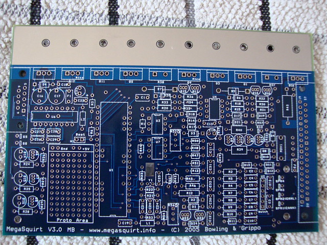
Blank Board
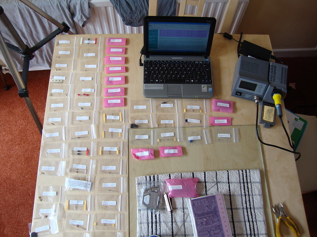
Setup ready to build
I brought a better soldering iron and also practised soldering once I was happy with my standard I went onto making the Jimstim board this went quite well but made some poor soldered joints, once they had been corrected I went into making the megasquirt, this all went well but you do have to make so choices while building on what options your going to run, I wanted to do away with the distributor so wasted spark and coil pack was needed so I decided on the Ford EDIS system. (If I was building now I would have used the VW wasted spark logic coil)
With the EDIS system the ECU was simplified which meant very little modifications needed. Once the ECU was built I then inspected all solder joints and setup the Jimstim to test the ECU, all tests completed it as then time to clean the board I removed the main processor and using electrical cleaner removed any flux left from the soldering once dry the ECU was assembled into it case and processor installed for the final time.

Fully built
Here a time lapse of the build:
Intake and Injection
On the VW beetle engine I like the look off the twin carburetor setup but this is also linked with distributor, fuel pump and linkage system all showing at the back (in the beetle this doesn’t matter as it covered but on the Trike it all exposed) so it needed to be simple and twin carb looking but injection and cheap.
After some looking I found a set of Honda CBR400RR throttle bodies with injectors for £10.50 of EBay. These are used on a inline 4 cylinder engine but looked like they could be split, after receiving them they do just unbolt in half and provide 2x 2 cylinder throttle bodies, there are some issues the idle speed adjustment screw was only on 1 half with a link rod connecting all 4 together and the fuel rail linked all 4 together.
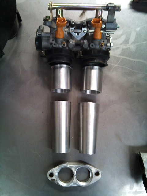
Throttle body with intake manifold sections
Fuel rail was simple cut in half and add the 4th missing mount to hold in place as it made off steel I welded on some an-6 fittings to each end and did away with there fuel pressure regulator.
I cut the fast idle/ idle speed rod in half and removed the coolant fast idle system (my engine is air cooled)
For the idle adjustment screw and rod supports I was bit stuck as I had 1 side but was missing the other after looking at making a new bracket and bush (I found another set of throttle bodies in eBay for under £15 so I brought these and borrowed the parts for the missing side)
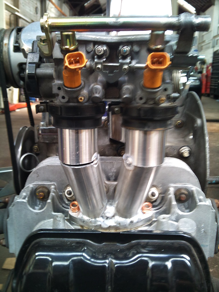
Intake ,manifold setup and welding
The throttle bodies mount to round stubs using rubber seals. I got my local engineering shop to make me some stubs and tapered tube to go from the throttle bodies to the VW intake size hole in Aluminium, as the original intake stubs are Aluminium I cut the old ones to leave me the bolt flange and welded the tubes onto them (excuse my Aluminium welding is not the best)
This gave me a nice neat looking all in 1 throttle and injector unit with a Throttle Position Sensor (TPS) built in.
Fuel System
Because the Trike had a carburetor before the fuel system needed quite a few changes.
First change was the going to be cosmetic (aero filler cap). Because there was not enough clearance between the body and tank I notched the top of the fuel tank to give me enough room to flush mount the filler cap.
While the fuel tank is out I changed the small feed and reverse outlets to an-8 these will now be feed and return for the fuel injection system. The lower fitting go straight into a high pressure fuel pump this then feeds a fuel filter then into the first throttle body round to the next throttle body then on to a fuel pressure regulator and should be straight back to the tank but as the old fitting was a reserve port it only just above the fuel out and I was worried about high pressure return fuel disturbing the fuel out.
I decided to make a little swirl pot to slow the return fuel down and stop it disturbing the fuel out. This also takes the an-6 hose and converts to an-8 for the tank.

Fuel tank, Fuel pump and Swirl pot
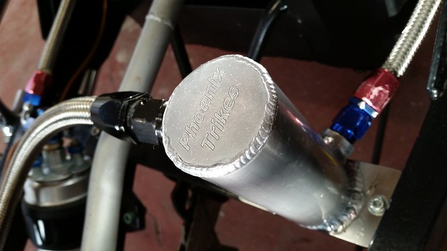
Swirl Pot
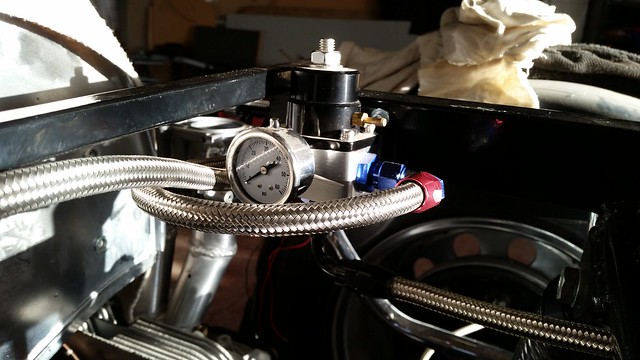
Pressure regulator
Ignition System
For the ignition system I wanted to run wasted spark and do away with the distributor to keep the engine looking very clean. When the project started the most simple way was to use the Ford Electronic Distributor Ignition System (EDIS) this setup only requires a crank sensor input (No cam sensor is needed). The Variable Reluctor (VR) crank sensor provides a signal from a 36-1 crank wheel mounted on the crankshaft, this signal is sent to the EDIS module that’s turns it into an RPM signal for the ECU, the ECU then provides a saw signal back to the EDIS to alter the ignition timing to the wasted spark coil pack.
The first job was to mount the 36-1 pickup wheel as the engine never came with one. Most conversions bolt this to the back off the crank pulley but as the Trike engine is on show I didn’t want this sticking out so I decided to mount it between the engine and pulley, this in turn made fitting quite difficult, we machined the back off the pulley to give us a flat surface then a spacer was made then using some aluminium, small neat grub screw secured it all together. Then the block of aluminium was machined to act as fuel pump blank and VR sensor mount.
A Mount was made on the main Chassis for the EDIS control unit. I then made a mount on the back off the fan housing for the wasted spark coil pack a set of Ford plug leads connect to the Beetle spark plugs.
A blanking bung was made for the hole where the distributor used to fit.
Coil pack mounting
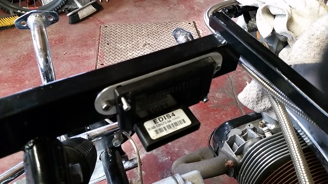
Ford EDIS
Sensors
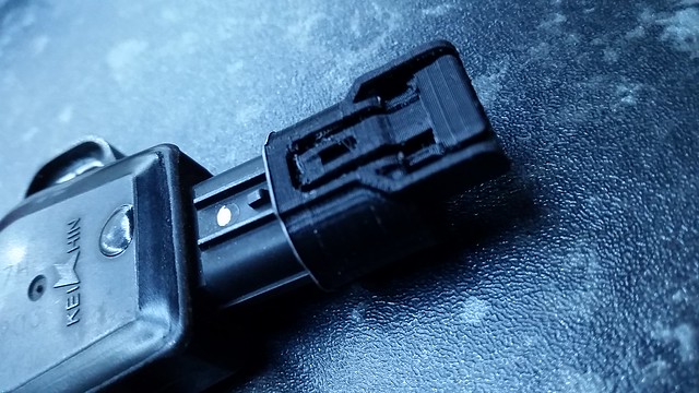
Throttle Position Sensor (TPS) this was easy as it came fitted on the throttle bodies (or so I thought). Until I tried to get the connector for the for the TPS, it took about 5 wrong connectors until I found what looked like the correct one, the only problem was the only place that sold them was in America and the connector was very cheap ($3) but with $15 shipping I didn’t want to order without checking, the company that makes the connector (sumitomo) have 3d drawing the only software on my computer that would open it was my 3d printer so I decided just to print it out. With a 3d printed connector it fitted the TPS so I ordered my connectors.
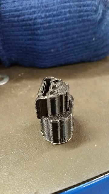
3d Printed TPS connector
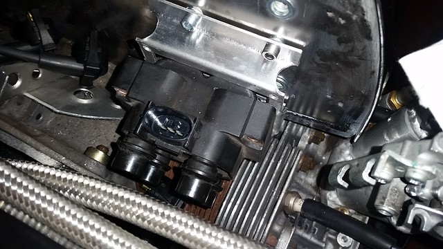
Coolant Temperature Sensor – As the trike is aircooled there no coolant but still need to give the ECU a temperature reading there debates on to what to measure (Oil or Cylinder head), looking at some newer fuel injection beetle engines they run a sensor in the head that pokes into the oil system by the rocker cover as my engine was a brand new Mexican engine it had the boss for this sensor built in, so after drilling the boss out and tapping the correct size thread I screwed the new sensor in.
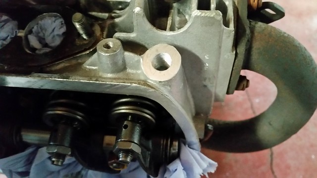
Drilled and tapped cylinder head boss
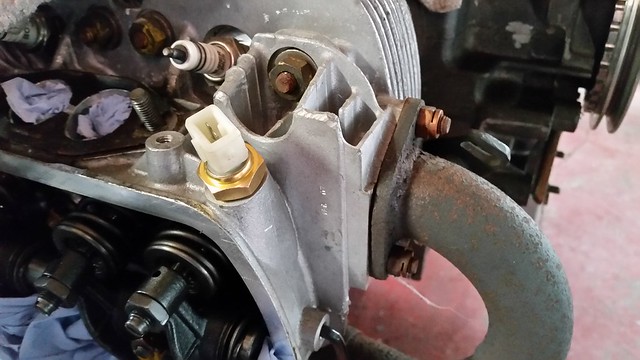
Sensor screwed in
Intake Air Temperature (IAT)
this sensor is going to be a VW open end IAT sensor this will be mounted below the air filter and above the throttle body.
Do to a change of plan with airfilters (the weber twin 40 air filter I was going to use hit the body) I changed to 4x little airfilters each filtering air for it own cylinder the IAY sensor was mounted in the top of one’s of these airfilters.
Manifold Absolute Pressure (MAP)
This is located in the ECU and the throttle bodies had vacuum ports on each one. So pipes run from each throttle body to a 5 way adapter and then onto the ECU.
Wiring Loom
I made the wiring loom from scratch. Made a list of which wires go where and what need to pass from the engine loom onto the main loom (Oil light, battery light, Ignitions feeds etc)
Next step was to source all the correct terminals and connectors, most were simple Junior Power Timer (AMP) some were Ford only (EDIS and Coilpack) the troublesome one was the TPS as listed above. For joiners in the loom I used these water proof connectors (Click here 2 Way, 3 Way, 4 Way , 6Way) For relays and holder click here. With all the connectors I tried my normal crimping pliers but wasn’t happy with theverything result so looked online only to find some very expensive (£800+) commercial tools. With these being way too expensive I found some pliers online that looked good and priced in my range so took a gamble, I ordered the PA-20 when these arrived I was so impressed I ordered the PA-09 for smaller applications (I’ve been told these work just as well on the automotive terminals)
More updates to follow
Really sorry for the lack of updates there have been lately.
Just a quick post keep you informed of what I’ve been up with, and let you know I’m still alive
We have made a water hoverboard that works on water.
Phoenix trike is coming on it unit fuel injection conversion
I have built 3 quadcopters
My VW Corrado G60 has sold but I still have my T5 van
Over the next couple of months I hope to get this all documented for you and put up on my blog for you.
© Toby Gardner