For the Wetlev V1 build please click here
For the Wetlev V2 build please click here
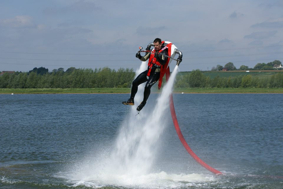
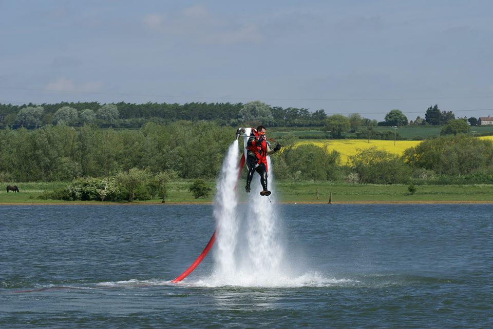
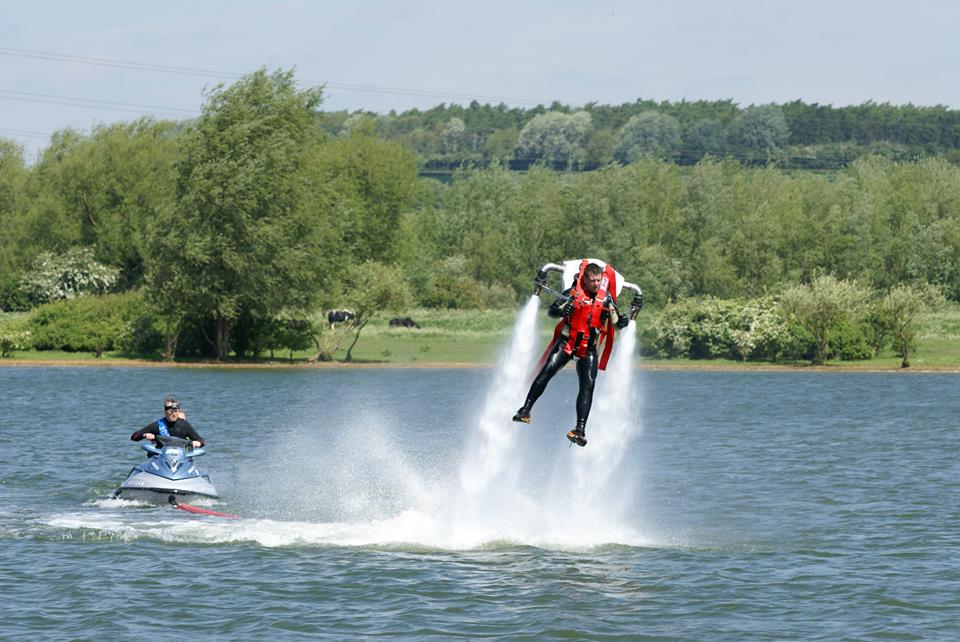
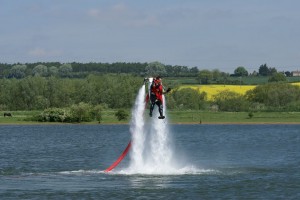
Here are some pictures off the latest flights:
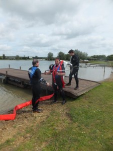
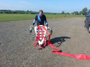
Dom first flight:
Bobby’s first attempt:
The testing seems to be good – 4500RPM to 6000RPM for the test (plenty more to go higher)
Steering needs stiffer limiting and going to lengthen the steering handles.
Update:
22/06/2013 – we made some small changes and gave us more control
We have been cracking on with the wetlev, as the season is coming to a start we thought it would be best to rebuild the supercharger on the 2006 Sea-Doo GTX jetski.
First thing to do was remove the supercharger – this is very simple and should take you about 1-2 hours. There lots off guides on the internet a quick search on the internet will provide many guides but a quick teardown is
- Remove seats
- Remove engine bay trims
- Remove inlet pipes
- Remove boost pipe
- Unbolt exhaust manifold and disconnect water pipe
- Remove exhaust waterbox strap
- Relocate exhaust
- Remove 3 bolts for supercharger and then slide supercharger out
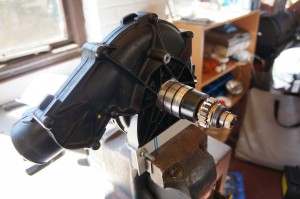
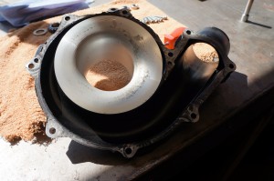
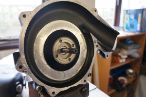
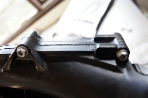
Once the supercharger is out you should see some thing like this:
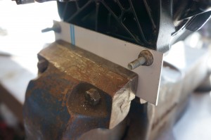
I made a bracket to support the charger in the vice:
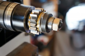
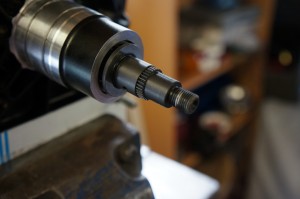
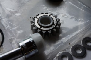
The important part is the gear drive with clutch unit:
First job is to grind down a 25mm spanner so it fits on the flats next to the gear, undo the 17mm nut the thread is a normal right hand thread. Once the nut is undone remove the sleeve and the dished washers that are part off the clutch unit. You then remove the first clutch washer, followed by the driver gear and needle bearings followed by the second clutch washer. Once all removed turn the supercharger round and we will start on the input side.
Remove all but 2 off the bolts around the outside off the supercharger unit, I then split the casing in 2 by pressing wedges between the lugs that stick around the outside once the casing has come apart remove the final bolts and separate.
Now refit the 25mm locking ring on the back off the supercharger and using a 17mm socket undo the supercharger impeller (this thread is Left hand so turn clockwise to undo) once undone remove the washer and the impeller and mounting base plus O ring.
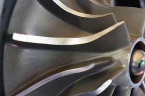
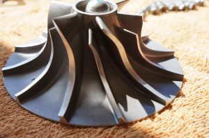
Inspect the impeller for damage this one looked very good.
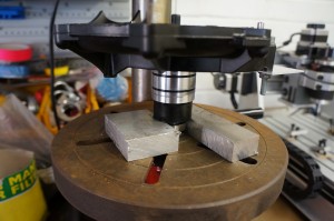
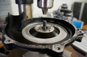
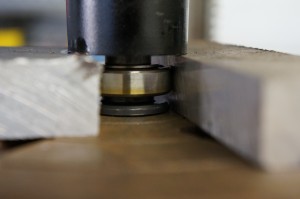
Next job is to press the shaft out off the supercharger housing. I sat the charger on so aluminium blocks and used a drill press to press the shaft out (the shaft came out quite easy with the bearing attached)
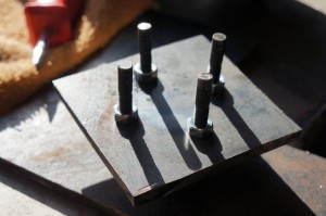
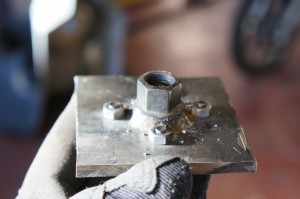
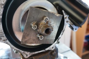
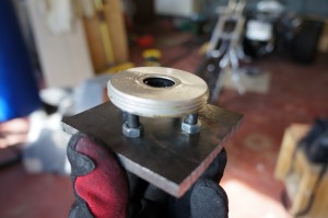
Now comes the part you need a special tool for, You need to remove the round aluminium cover that is the inner bearing cover. Because I dont have any special tools I made my own version. Using some 6mm steel plate I marked a 44mm diameter circle, I then marked a cross through the center off the circle then drilled a 6mm hole at each intersection point using a 6mm shanked bolt with the head cut off and using 2 nuts to hold it into the plate. I then welded an old wheel nut to the other side.
After heating the supercharger housing to release the loctite the tool was used to undo the cover
This cover proved to be very tight and took 2-3 attempts off heating and trying to get it undone.
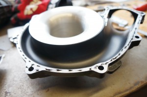
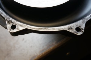
At this stage with everything removed I clean both sealing faces on the supercharger and also completely cleaned all the housings
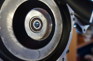
Next was to reinstall the bearing under the cover
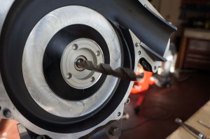
Reinstall the bearing cover and using a drill bit I placed the shaft support in the back half (This stage was not needed as the main shaft and other bearing should be built as unit and pressed into this bearing)
Press the bearing onto the shaft and fit all the sleeve’s and spacers in the order they came out, Now press the complete assembly into the supercharger and other bearing
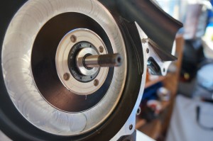
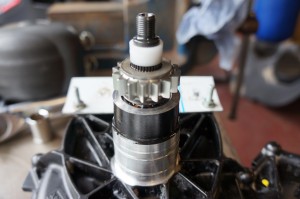
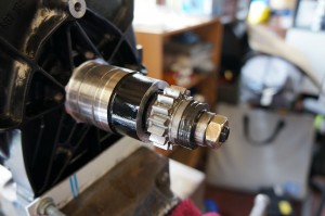
Now you should end up with this sticking out
Press the new seal in and fit the O ring and impeller mounting flange
Now refit the impeller (remember nut is Left hand thread) and torque to correct setting. Now apply a very thin film off sealer around the edge off the supercharger (most people use way to much and anything that squibs out will squib inside as well and go round the engine!!)
Now bolt both sections back together
A very very slight squib 🙂
Now we start back on the drive side off the supercharger, start by soaking the new supercharger washers with oil and install 1 onto the shaft.
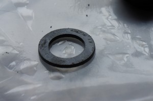
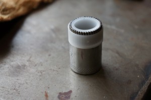
I used a socket to act a press for installing the needle washers into the drive gear
I then very carefully installed the drive gear onto the shaft taking care not to loose and needles rollers
I popped some more oil on the needles rollers and installed the other washer
Reinstall the locking tab and clutch washers in the order shown on the sheet, fit the nut and torque the nut.
Now lock the drive pulley and using the torque wrench set to 8nm and check the torque wrench clicks before the clutch slips
Now set the torque wrench to 14nm and check the clutch slips before the torque wrench clicks. If yes (which it should) then great if not recheck your spring washers.
Reinstall the 2 rubber O rings and refit the charge and enjoy!
For the Wetlev V1 build please click here
For the Wetlev V2 build please click here
After a unsuccessful first test flight with the Version 2 Wetlev (We suffered from excess pressure in the nozzles blowing the boot open) We made the opening in the nozzles 12mm bigger this allows more water to flow at the expense off some free play in the steering. The first flight was successful with some long flights and some time to learn the steering controls.
Here are some pictures:
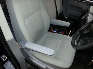
How to fit Armrests to a Volkswagen Transporter T5 seat
What you will need:
- Armrests
- Mounting Brackets (Most come in a kit)
Start by moving your seat as far up as it will go and tilt the backrest as far forwards as possible. Now remove the 2 screws that hold the up/down adjuster on and remove the up/down handle. Now move to the back off the seat and pull the centre plastic trim towards the rear off the van working around each side pulling the trim away from the seat loosen the trims down each side but there no need to remove them.
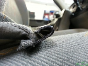
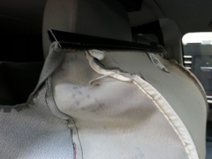
Now follow the rear fabric down to the bottom off the seat and you can feel a seam at the bottom, this seam is where the backrest cover joins. They use a U shaped channel section with a clip style fixing on the other side. By sliding a screwdriver and with a lot off care open the channel and unclip the seat cover. Gently ease the cover up at the rear and about a 1/4 way from each side there a metal rod that clips into a hole – unclip these as these hold the cover tight to the foam.
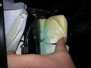
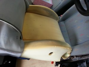
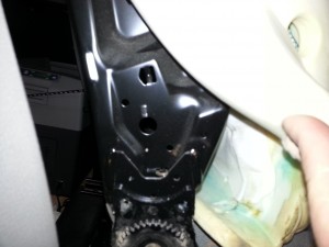
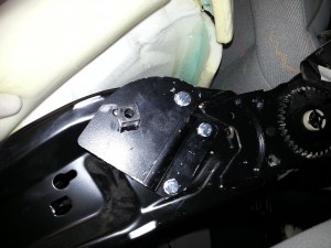
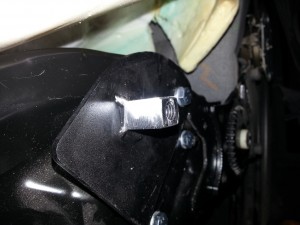
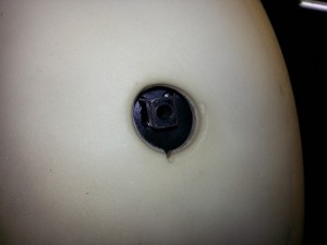
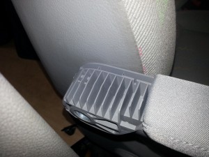
By lifting up each side off the cover you should be able to work the cover up the seat and give yourself access to armrest mounting points, move the foam and you should be able to see the the metal framework. Offer up the brackets and make sure they line up with the holes. Now check the brackets fit into the armrests (On mine I found the long plane was too long and I had to sand them down a little) Once they all fit bolt the brakets to the seat frame and check the bolts are tight, Refit the foam support and check the square is in the hole.
Now pull the seat cover back down and refit the 2 metal wires, Once they are fitted pull the seat cover down and check fitments if it all looks good refit the clip by folding the U channel back on itself and inserting the clip in.
Now refit the trims and handles, Make sure the seat cover is nice and tight. Using you fingers find the square through the cover and using a sharpe knife cut the square shape out. Now fit the arm rests using a 6mm Allen key and fit the cover and now enjoy your lovely new arm rests.
If you follow my blog you would have seen the test flight off the Wetlev V1
As this seem to work very well for some old exhaust tube and a sheet of aluminuim we have decided to build a Version 2.
The main aims
- Lighter
- More upright when floating
- Better and smaller nozzles
- Water proof metal
- Better seat and harness
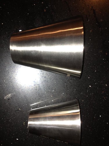
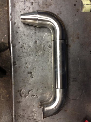
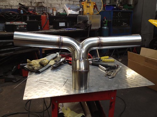
We started out by seeing what parts we could buy “off the shelf”, this proved quite sucessful with 90deg bend and reducers all available in stainless steel after ordering everything we needed we set about doing the basic design and layout of the tubes.
Much was taken from V1 but some changes were made, the centre Y piece was raked so the pipes split and also move forward very slightly this should bring the nozzles more inline with the person wearing the pack
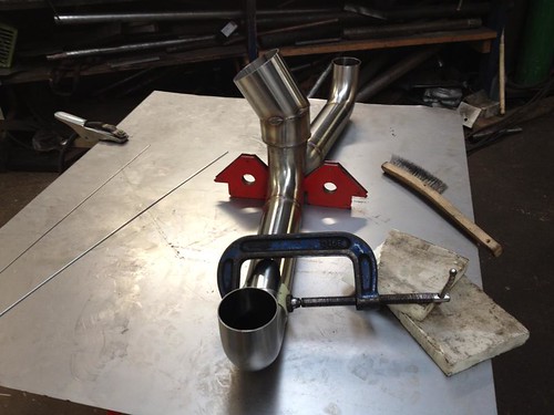
All the parts are welded together using a TIG welder and stainless steel rods. (It been over a year from the last time we used the TIG welder! makes up for the ugly welds)
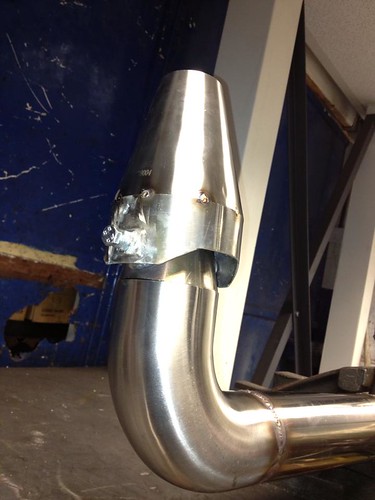
Next job was to make the steering nozzles and weld these together and machine the steering pivot bosses.
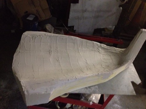
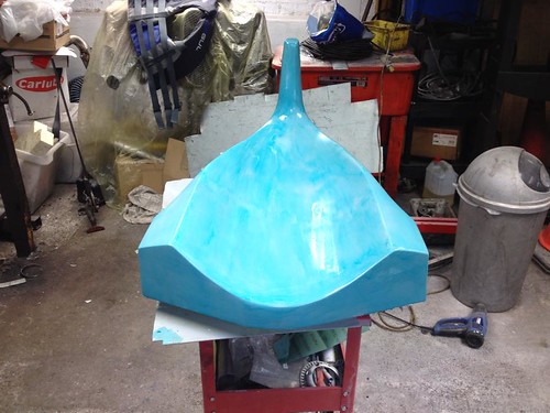
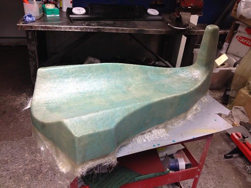
Next we turned to the seat/backing/buoyancy. We decided to make a design out of foam and then cast a mould from the foam. This have the option to make copies if we needed to make changes.
Once the fiberglass had set we trimmed the side and made a flange to go all the way around the outside, this gives the mould extra strength and also provides and good edge for making copies.
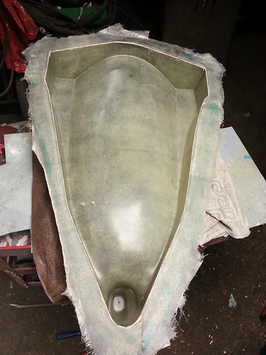
Once the flange was dry we removed all the foam and filler to leave us with a nice fiberglass mould.
To be updated very soon 😉
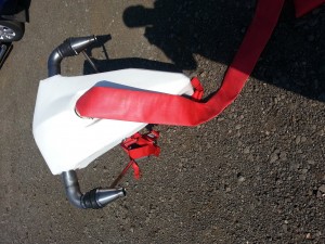
I’ve still got to finish the build write up but here some pictures off the finished Wetlev V2
Here some photos off the test flight:
Video on Youtube
More testing can be found by clicking here
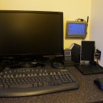
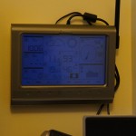
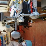
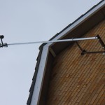
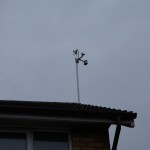
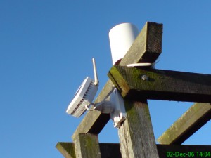
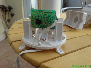
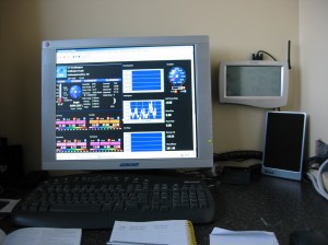
If anyone has been a long time follower of my website you will know I used to have my own weather station on my house that provided real time updates of the weather in Great Doddington, Northamptonshire. This was setup in November 2006 and had been running with very little problems until early 2012 when the rain gauge stopped working, I took the sensor apart but the circuit board had rotted away. This was shortly followed by the wind direction and speed sensor. Here are some pictures off the old setup.


Knowing I needed a new station I started looking around but some vital house items needed doing so the weather station got delayed until now.
I have just installed a Oregon Scientific WMR200 weather station with extra UV sensor.
As the old unit had already been installed I started by installing the new display unit. This was simple enough apart from the new unit is USB and the old was serial
Next step the rain and UV sensor were fitted, the best place I found was on the woodwork at the bottom off the garden
Next the Wind speed and direction were mounted along with the outside temperature sensor, These were mounted on to a 10 foot x 1.5″ pole
Then this was pole was mounted to the side of my house to give a good clear open view off the wind
The control unit was then connected to my new server running Windows Home Server (WHS) and the OS software was installed. This was then linked upto the Weather Display software. The weather display software then uploads the data to my webhosting were it then converted to a flash file for easy viewing.
Great Doddington Live weather Station (Click here)
Me and Dom (mostly Dom to be honest) have been building our homemade copy off the american Jetlev.
First we made the feed pipe and bends to direct the water back down to earth (some exhaust tubing we got bent locally)
Next we mounted some aluminium for the back support, (this was trimmed down later to save weight)
Next we put some cuts into a straight tube and folded the ends together to form the nozzles
After making some pivots for the nozzles we gave it a quick coat of paint
After putting it together and putting on a harness made out off seatbelts and 4 point harness. Strechy CV boots were used as covers for the nozzles – ready for it test flight
And here we have the videos off the first ever wetlev test flight
Dom with his first test flight
More pictures check out the set on flickr
This is a guide to turning on comfort windows (Windows controlled by the key) on a T5 VW Transporter.
Tools you will need:
- A T5 van with factory remote central locking and factory electric windows.
- An old computer/laptop with ms-dos – Basic skills in MS-DOS
- Serial lead to connect to your car (Search – KKL COM port cable)
- VDS pro
- Battery support unit (optional but recommended) I use a Ring Smart Charge Pro 35
If the battery voltage drop too low when performing the programming the ECU might become unusable
How to do it:
Remove battery cover and connect battery support unit.
Wait for the set voltage to be reached
Now connect the lead to the T5 van and to the computer
Boot the computer into ms-dos

Using dos commands like dir/w find VDS pro and load program by typing VDC_E.EXE
(If you unsure try
r: – Press enter
dir/w – press enter
VDC_E.EXE – press enter)
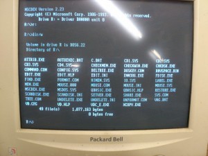
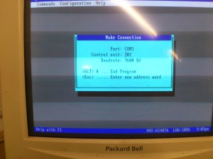
VDS pro will try to connect to your car, if successful great if not try changing the com port.
Once connected you need to select central convenience module (CCM) type number 46
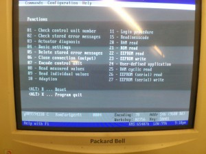
Once connected to the CCM you need to login. Type 11 and then login 19283
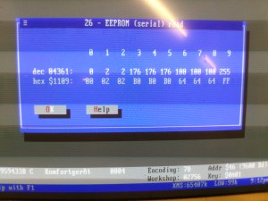
Now you want to read EEPROM, type 26. Now choose your memory location, type 04361 – Make a note off all the readings
- You should have something along the lines off 0,10,10,176,176,176,100,100,100,255. The first 3 are the important ones
- In binary code works like this 128,64,32,16,8,4,2,1
- So 0= 00000000 10=00001010 (because we have 1 in the 2 and 8 positions add them together =10)
- We need to change the 10 to 2 so it works like this 2=00000010
We now need to change the value so type 27 now enter 04362 and 02
We now need to change the value so type 27 now enter 04363 and 02
Now press ALT-X
Unplug the lead and now test your now comfort windows
VW Factory bluetooth retrofit to 2010 VW Scirocco with RCD510 radio
After doing a lot of research on the Fiscon Bluetooth and the VW factory kits I decided on the factory one. The reason is the integration into the factory MFA display (white version), full use of the multi function steering wheel and the factory version being cheaper (more on this reason later).
What you need:
- Factory Bluetooth kit – Ebay or the like
- CAN-BUS repair wires – 000-979-987
- Fabric tape – 000-979-950
I brought the cheap factory Bluetooth retrofit kit off Ebay this was great value at under £200 but when I reading up I noticed a lot of people saying the CAN-BUS wire are not twisted like the VW specification states, this was fine by me as saving some money and modding/hacking is right up my street.
First thing was to work out which were the CAN-BUS wires these went into pins 18/17 in the 54pin bluetooth plug and this feeds into pins 10/9 in the quadlock connector (So CAN-LOW = T54/18 into T16/10 and CAN-HIGH = T54/17 into T16/9), Next I removed the cover off the bluetooth plug (T54) and removed the pins (because I didn’t own any of the small pins I disassembled the wires from the terminals) I now crimped and soldered the CAN-BUS repair wires into the terminals and refitted them back into the plug and un-taped the loom removed the old cables and re-taped the new CAN-BUS ones in.
I now moved onto the Quadlock end (T16) the link wires between the male and female quadlock connectors were also untwisted so I remove these wires, as the quadlock connector used standard power timer terminals I has some new ones of these. One end I crimped and soldered some more of the repair wires at the female end I joined both the quadlock and bluetooth connectors together to give my T off with very little untwisted cables. Taped up the wires and the loom now it ready for fitting.
As this kit covers many cars and there are many good guides like Octavia-VRS guide. I wont go into too much details on the install other then these features:
To be installed properly a lot needs to be removed.
The factory bluetooth unit fits under the drivers seat to fit the wiring in correctly I found it best to remove the drivers seat, sill trim and drivers lower dashboard.
The main loom then sits behind the radio so I removed the radio unit.
The microphone wire runs up the Left A pillar so I removed the glove box and A pillar trim I also dropped the headlining down and remove the interior light unit.
Mounting points under drivers seat
Where to run the wires down the sill
A fair amount of the car stripped apart
VW Microphone that mounts behind the interior light unit
Once everything is back together and installed re-connect the battery and using VCDS carry out a full autoscan. Once complete check there no new fault codes (you might have one saying steering angle sensor – this is normal – Use this guide to rectify the fault) Now we re-code the 19- CAN-Gateway to say we have 77- Telephone installed. when the code is saved disconnect VCDS and switch of the ignition and wait about 45 seconds. Re-connect VCDS and re-autoscan the car. Now enter 77- Telephone and check the coding is correct for your options, do the same for 56- Radio and 16- Steering wheel. Once complete disconnect VCDS and ignition off again. Restart and enjoy your new bluetooth kit 🙂
Connected to my phone
Phonebook integration that works through the RCD510 or the MFA/DIS
I’ve been running led down lighters in my corrado and love the effect, so I made the choice to fit the passat W8 interior light into my T5.
What you need:
- VW Passat W8 interior light – VW or Ebay your choice
- Wiring plug – 893-971-993
- 2x Repair wires – 000-979-103
- 1 way superseal connector, male and female
- Soldering Iron and solder
- Heat-shrink
How to do it:
Power everything off and disconnect the battery, remove the light lens off the old light and remove the 2 cross head screws, there are 2 plastic tags one each side that need to be flicked in and remove the old light unit.
In the hole the light has just come from there might be a little adaptor plate that needs to be removed.
Test fit the new light and you might find it hits against the cubby hole, a lot of guides show you chopping the corner out of the cubby hole.
I went for a different approach, With a sharp blade trim all the plastic off where the wiring plug should go (you should have the original terminals sticking out) now carefully bend the terminals up over 90 degs.
Now we solder the repair wires directly to the terminals off the interior light, cut the repair wires in half and solder 3 off them to terminals 3-4-5, once complete solder a length of wire to terminal 1 (I soldered a short length of wire the this pin and used the 1 way superseal connector so the light can be removed if needed) Heat-shrink all the terminals on the passat light.
Once all soldered onto the Passat light you then you need to put the pins in the correct position on the adaptor plug,
- Passat W8 light –
- Pin 1 – Connect to pin 17 on the back of the light switch
- Pin 3 – Pin 1 on adaptor plug
- Pin 4 – Pin 3 on adaptor plug
- Pin 5 – Pin 2 on adaptor plug
Once finished it should look something like this:
Now you fit the light by hooking the back edge in and pressing the front edge up into place. Connect the wire to the light switch up, re-connect the battery and enjoy all your hard work 🙂
© Toby Gardner

